AI-Ready Datacenter Architecture: The 2026 Definitive Guide
AI-ready datacenter architecture the digital foundation of the 21st century is undergoing a phase change. However, the sudden and massive demand for large-scale model training and real-time inference has rendered these legacy environments structurally insufficient. We are no longer simply moving data; we are orchestrating massive, non-linear computational bursts that require a fundamental rethink of thermodynamics, networking, and power delivery.
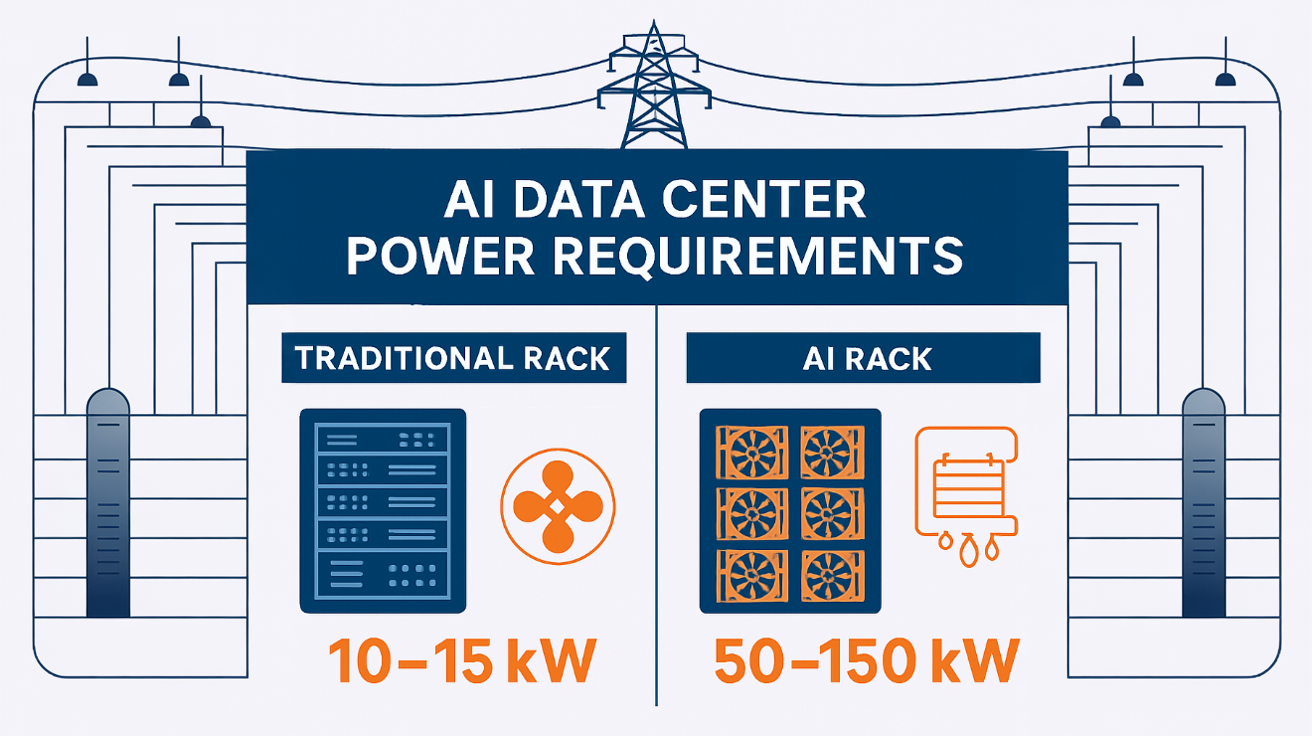
The transition to a high-density, accelerated computing environment is not merely an incremental upgrade; it is a total systemic overhaul. High-performance GPUs and specialized accelerators consume power and generate heat at levels that dwarf the capacities of traditional enterprise facilities. Where a standard server rack might have pulled 5 to 10 kilowatts (kW) in 2020, a modern cluster focused on heavy-duty model processing can easily demand 50 to 100 kW per rack. This five-to-tenfold increase in power density forces a move from air cooling toward liquid-to-chip solutions and necessitates a massive expansion of the “Rear-Door Heat Exchanger” (RDHx) infrastructure.
Beyond the physical constraints, the logical topology of the facility must also evolve. The traditional “Spine-Leaf” network architecture is being stretched to its breaking point by the “East-West” traffic demands of distributed training. When thousands of accelerators must remain in perfect synchronization to process a single model layer, microseconds of latency become millions of dollars in wasted compute time.
This article serves as a definitive reference for architects, engineers, and infrastructure strategists navigating the complexities of high-density compute. This is an inquiry into the engineering of the invisible, where the success of the most advanced digital models depends entirely on the gauge of a copper wire and the flow rate of a cooling loop.
AI-Ready Datacenter Architecture
To effectively analyze AI-Ready Datacenter Architecture, one must first dismantle the assumption that it is a specialized subset of standard IT infrastructure. In a professional editorial context, this architecture is defined by its “Density-First” philosophy.
Multi-Perspective Explanation
From the perspective of a mechanical engineer, the architecture is a “Thermal Management Challenge.” It is about the physics of heat transfer in high-density environments where air is no longer a viable medium. From the perspective of a network architect, it is a “Fabric Challenge,” focusing on Non-Blocking architectures and RDMA (Remote Direct Memory Access) over Converged Ethernet (RoCE) to ensure that data moves between accelerators with near-zero friction.
Oversimplification and Risks AI-Ready Datacenter Architecture
A common oversimplification is the “Retrofit Fallacy”—the belief that a legacy data center can become “ready” simply by adding liquid-cooled racks. The risk of ignoring the “Holistic Stack” is a facility that is technically functional but operationally fragile, prone to localized “Hot Spots” and power-trip events that can corrupt massive, weeks-long training runs.</p>
Deep Contextual Background: The Evolution of Compute
The history of the data center has moved through three distinct eras. The first was the “Mainframe Era,” characterized by centralized, highly proprietary systems. The second was the “X86/Cloud Era,” which prioritized horizontal scaling, virtualization, and the commoditization of hardware. We have now entered the “Acceleration Era,” where the focus has shifted from the quantity of servers to the quality of the interconnect and the density of the compute.
In the previous era, “Efficiency” was measured by how many virtual machines could be squeezed onto a single CPU. Today, efficiency is measured by “FLOPs per Watt.” The shift from serial processing (CPUs) to parallel processing (GPUs) has fundamentally changed the “Compute-to-Power Curve.” This puts unprecedented stress on the “Uninterruptible Power Supply” (UPS) and the backup generator systems, which were never designed for such sustained, high-amplitude demand.
Conceptual Frameworks and Mental Models AI-Ready Datacenter Architecture
To evaluate high-density architecture with professional depth, we utilize specific mental models:
1. The “Compute-Thermal-Power” Triad
Every design decision is a trade-off between these three variables. An “AI-Ready” facility is one where these three variables are in perfect “Dynamic Equilibrium.”
2. The “Fat-Tree” Networking Framework
Traditional networks are designed for a “North-South” flow (users accessing data). Training workloads are “East-West” (servers talking to servers). The Fat-Tree model ensures that every accelerator has multiple, non-congested paths to every other accelerator.
3. The “Liquid-to-Chip” Logic
This model assumes that air cooling is a legacy constraint. By moving the coolant directly to the heat source (the silicon), we can increase rack density while simultaneously lowering the energy spent on fans. This framework shifts the “Primary Resource” from air-conditioned space to “Chilled Water Flow Rates.”
Key Categories: Physical and Logical Typologies
Remediating or building for acceleration requires a taxonomy of systems categorized by their “Cooling Medium” and “Network Fabric.”
Realistic Decision Logic
The decision to utilize AI-Ready Datacenter Architecture is driven by the “Training vs. Inference” ratio. If a facility is primarily for inference (serving models), traditional air cooling with slightly higher density might suffice. If the goal is training (creating models), the “Thermal Barrier” is reached almost immediately, making liquid cooling a structural requirement rather than an optional upgrade.</p></p>
Detailed Real-World Scenarios AI-Ready Datacenter Architecture
Scenario 1: The “Legacy Grid” Bottleneck
A firm attempts to install 20 H100 GPU racks in an older 2MW facility.
-
h-to-node=”37,0,0″> data-index-in=””>-node=”0″>The Conflict: The racks require 40kW each, but the floor’s electrical distribution is capped at 12kW per rack.</p></p>
-
a-index-in-node=”0″>The Failure: The “Power Whip” cables overheat, and the UPS fails to handle the “Inrush Current” when the GPUs start their first batch.</p></p>
-
The Solution: Installing a “Busway” system that allows for flexible power taps and upgrading to “Lithium-Ion BESS” for better surge handling.
Scenario 2: The “East-West” Congestion
A mid-sized provider builds a GPU cluster using standard Top-of-Rack (ToR) switches.
-
Training time for a 70B parameter model is 4x longer than estimated despite 100% GPU utilization.</p></b>
-
-node=””The”> The network is oversubscribed. GPUs are “stalling” while waiting for “All-Reduce” operations across the cluster.</p></b>
-
The Fix: Redesigning the topology with a “Non-Blocking” optical fabric.
Planning, Cost, and Resource Dynamics AI-Ready Datacenter Architecture
The economics of high-density infrastructure are characterized by a shift from “Real Estate Costs” to “Infrastructure Intensity.”
Direct vs. Indirect Costs
-
Direct: Power distribution units (PDUs), specialized racks, liquid cooling manifolds, and high-speed optics.
-
Indirect: “Design Latency” (the time to engineer specialized systems), water treatment chemicals for cooling loops, and the specialized labor required to maintain high-pressure plumbing in a data room.
Relative Resource Impact (Per MW of Capacity)
Tools, Strategies, and Support Systems
The successful operation of accelerated compute requires a “Digital-to-Physical” management stack:
-
- a-path-to-node=”51″><
li>
ss=”yoast-text-mark”>data-path-to-node=”51,0,0″ data-index-in-node=”0″>DCIM with “CFD” (Computational Fluid Dynamics): Real-time modeling of airflow and
-
-
-
-
-
-
- =”1″ data-pa=””>th-to-no
</ol>de=</
-
ol>
-
“51”>water flow to</ol
-
></li></li><
-
-
/ol>predict hot spots before they occur.</p></p
-
- >
-
- <p data-path-to-node=”51,1,0″>th-to-node=”51,1,0″ data-index-in-node=”0″>AI-Driven Power Shifting: Software that monitors utility rates and shifts “Batch Training”
- ata-=””>path-to-node=”51″>
- >>
- =””>ode=”51″>workloads to off-peak hours or when renewable energy i
-
-
Automated Leak Detection: String-based and point-based moisture sensors integrated into the “Plinth” of every liquid-cooled rack.
- <p class=”yoast-text-mark” dat
-
- t=”1″ data-path-to-node=”51″>
-
- a-path-=””>to-node=”51,3,0″&g
</li>
t;
-
-
s peaking.</p></li>
-
Optical Signal Monitoring:
- tyle=”list-style-type: none;”>
-
- Tools that trac
k “Bit Error Rates” on 400G/800G links to identify failing transceivers before they cause a cluster-wide hang.</p></li>
-
-
Busway Power Distribution: Replacing traditional “Rope” power cables with rigid, modular overhead rails that handle higher amperages.
-
CDU (Coolant Distribution Units): The “Heart” of the liquid system, managing the heat exchange between the internal facility loop and the external building loop.
Risk Landscape and Failure Modes ts-root=”1″>AI-Ready Datacenter Architecture
The “Risk Profile” of high-density architecture involves “Compounding Failures” where a small mechanical event leads to massive structural or data loss.
<ul data-path-to-node=”55″>
-
-
-
data-path-to-node=”55,0,0″><b>-path-to-node=”55,0,0″ data-index-in-node=”0″>The “Thermal Runaway” Window:
</ul
-
-
>ta-path-to-node=”32″>In an air-cooled rack pulling 40kW, if the fans fail, the hardware will reach “Critical Temperature” in less than 30 seconds.</p><ul
-
-
- >
-
-
Chemical Corrosion: Improperly treated water in a cooling loop can cause “Pitting” in the cold plates. Over 18 months, this leads to microscopic leaks that can destroy a million-dollar GPU chassis.
-
Optical Fiber “Macro-bends”: In a high-density 800G environment, even a slight pinch in a fiber optic cable can cause signal degradation that triggers a re-transmit loop, tanking the performance of the entire training cluster.
-
-
-
Governance, Maintenance, and Long-Term Adaptation
Maintaining an accelerated facility requires “Forensic Governance”—a move away from “Break-Fix” toward “Predictive Lifecycle Management.”
-
-
-
- th-to-node=”59″>
-
<b data-path-to-node=”59,0,0″ data-index-in-node=”0″>Review Cycles: Quarterly “Water Chemistry” audits and semi-annual “Optical Cleaning” of all primary fiber trunk lines.
</li></li>
-
h-to-node=”59,1,0″><b class=”yoast-text-mark”>a-pa=””>th-to-node=”59,1,0″ data-index-in-node=”0″>Adjustment Triggers: If “Rack Delta-T” (the difference between inlet and outlet temp
- erature) varies by more than 5 degre</p>
- es from the baseline, it triggers an immediate investigation into the coolant flow valves.</p>
-
The Layered Checklist:
-
Post-Installation: “Pressure Test” every cooling loop at 1.5x operating pressure for 24 hours.
-
Year 1: Inspection of “Flexible Hoses” for signs of brittleness or elastomer fatigue.
-
=”59,2,1,2,0″>Year 3: Assessment of “Power Factor Efficiency” to ensure the utility transformers aren’t being over-saturated.
-
-
-
-
Measurement, Tracking, and Evaluation ts-root=”1″>AI-Ready Datacenter Architecture
- le=”list-style-type: none;”>
-
-
- class=”yoast-text-mark” data-path-=””>
-
-
- to-node=”63
“>
-
-
ata-path-to-node=”63,0,0″>“”>th=””>-to-node=”63,0,0″ data-index-in-node=”0″>Leading Indicators: “T-PUE” (Total Po
- >
- ta-path-=””>
-
- wer Usage Effectiveness)—including the power use
d by the IT fans, which standard PUE often ignores.</p>
- </p>
-
<li>
-
-
-
-path-to-nod=””>e=”63,1,0″>-path-to=””>-=””>node=”63,1,0″ data-index-in-node=”0″>Lagging Indicators: “Cluster
-
- <li style=”list-style-typ
- e: none;”>
-
-
- ass=”yoast-text-mark” data-path-=””>Uptime” during multi-week training runs.</p></li>
-
Quantitative Signals: “FLOPs per Rack”—the literal compute density of the facility.
-
Documentation Examples:
-
The “Thermal Map”: A live 3D visualization of the facility floor.
-
Water Treatment Logs: Documenting the pH and conductivity levels of the secondary cooling loops.
-
-
-
to-node=”65″>Common Misconceptions and Industry Myths
-
-
- tart=”1″ data
-path-to-node=”51″>
-
-
-
- s=”yoast-text-mark” data-path-to=””>-node=”66″>
-
th-t=””>o-node=”66,0,0″ data-index-in-no=””>de=”0″>Myth: “Liquid cooling is too dangerous for data centers.”
-
- ta-path-to-
node=”66,0,1″>
-
- ass=”yoast-text-mark” data-pa=””>th-to-node=”66,0,1,0,0″>ata-path-to-node=”66,0,1,0,0″ data-index-in-node=”0″>Reality: With modern “Quick-Disconnect” valves and dielectric fluids, liquid cooling is often safer for the hardware than pushing air through dusty filt
-
- ers.</p></p>
-
-
Myth: “Cloud AI makes on-premise AI-Ready architecture obsolete.”
-
de=”0″>Reality: For large-scale proprietary training, the “Data Gravity” and “Egress Fees” of the cloud often make a dedicated, high-density on-premise facility more cost-effective.
-
-
ata-p=””>ath-to-node=”66,2,0″ data-index-in-node=”0″>Myth: “Standard Ethernet is too slow for AI.”
<ul class=”yoast-text-mark” data-pat=””>h-to-node=”66,2,1″>
- ass=”yoast-text-mark” data-path-=””>to-node=”66,2,1,0,0″>data-path-to-node=”66,2,1,0,0″ data-index-in-node=”0″>Reality: While InfiniBand was the leader, RoCE v2 on high-end Ethernet swi
- tches has closed the gap for all but the most extreme low-latency research cases.</p></p>
-
Conclusion
The architecture of the data center has ceased to be a passive container for hardware and has become an active participant in the computational process. To build an AI-Ready Datacenter Architecture is to accept that the constraints of the physical world—gravity, heat, and electricity—are the ultimate governors of digital progress. By prioritizing thermal density, non-blocking fabrics, and resilient power delivery, infrastructure leaders can move past the limitations of the legacy “General Purpose” model and build the foundations for the next era of intelligence.