On-Site Microgrid Stabilization: The 2026 Definitive Guide
On-site microgrid stabilization the decentralization of the electrical grid is no longer a peripheral experiment in sustainability; it has become a fundamental requirement for industrial and institutional continuity. As the primary macrogrid faces increasing volatility—driven by aging infrastructure, climate-induced thermal stress, and a rapidly changing generation mix—the ability to maintain local power equilibrium has emerged as a high-stakes engineering discipline.
At the core of this transition is a complex balancing act known as frequency and voltage regulation. These resources lack natural inertia, meaning that even a minor fluctuation in cloud cover or a sudden spike in industrial motor load can lead to catastrophic instability.
In a traditional grid, power flows in one direction—from the utility to the consumer. In a decentralized environment, power flows are bidirectional, requiring advanced sensing and switching technologies to prevent “Islanded” systems from back-feeding into a downed utility line. This article serves as a definitive reference for those tasked with designing and governing these systems, moving beyond the surface-level marketing of “Energy Independence” to address the deep structural logic of maintaining a stable, autonomous power environment.
Understanding “On-Site Microgrid Stabilization”
To engage with On-Site Microgrid Stabilization is to recognize that power quality is a dynamic negotiation between supply and demand that must be resolved in milliseconds. In a professional editorial context, stabilization is defined by the system’s ability to maintain its “Nominal Frequency” (60Hz in North America) and “Voltage Profile” regardless of external grid conditions or internal load transients.
Multi-Perspective Explanation
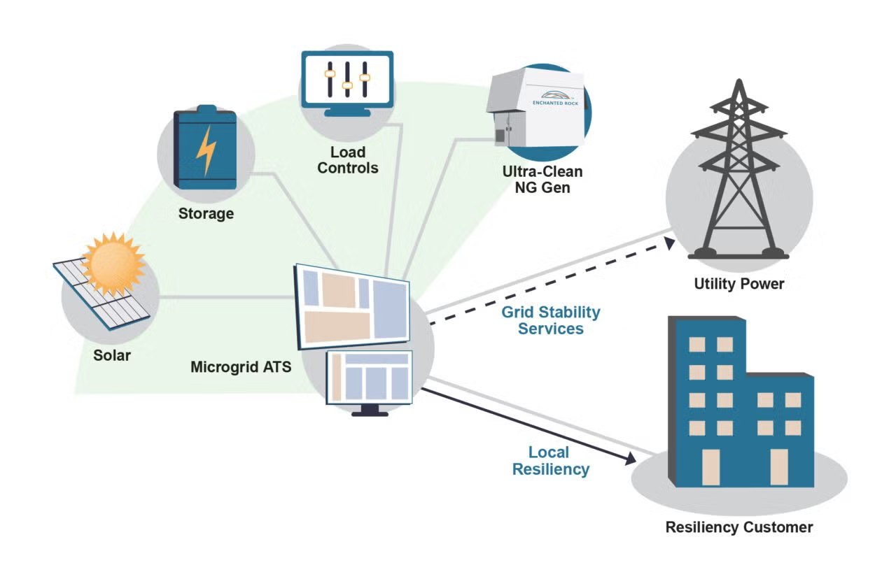
On-site microgrid stabilization from the perspective of a power electronics engineer, stabilization is a “Control Theory” problem, focusing on the tuning of inverters to act as “Grid-Forming” assets. From a facility manager’s view, it is a “Business Continuity” problem, where the metric of success is the “Seamless Transition”—the ability to disconnect from the macrogrid during a brownout without the flickering of a single LED or the rebooting of a single server. From an economic perspective, it is a “Demand Side Management” opportunity, allowing a facility to “Arbitrage” power by using stored energy when utility rates peak.
Oversimplification and Risks On-Site Microgrid Stabilization
A recurring risk in this field is the “Storage Over-simplification”—the belief that simply adding batteries will solve stability issues. While batteries provide energy capacity, they do not inherently provide the “Synthetic Inertia” needed to dampen rapid frequency deviations. The risk of ignoring the “High-Speed Control Layer” is a system that can provide power for four hours during a blackout but collapses the moment a large elevator motor starts up, due to an uncorrected voltage sag. True stabilization requires a marriage of energy capacity (kWh) and instantaneous power response (kW).
Deep Contextual Background: The Inertia Gap
The historical stability of the global grid was a byproduct of the “Big Iron” era. As we retire these thermal plants in favor of “Inverter-Based Resources” (IBRs) like wind and solar, we are effectively removing the “Shock Absorbers” from the electrical system.
This transition has created the “Inertia Gap.” In a localized microgrid, this gap is magnified. Without the vast reserves of the macrogrid to lean on, the on-site system must generate its own “Virtual Inertia.” This is the technological foundation that allows a hospital, data center, or military base to operate as a self-sustaining “Electrical Island.”
Conceptual Frameworks and Mental Models On-Site Microgrid Stabilization
To evaluate microgrid performance with professional depth, we utilize specific mental models:
1. The “Energy vs. Power” Distinction
A robust stabilization strategy uses ultra-fast assets like flywheels or supercapacitors for the first 500 milliseconds of a disturbance, allowing the slower battery systems or backup generators time to ramp up.
2. The “Load Shedding” Hierarchy
This model views the facility’s electrical demand not as a single block, but as a prioritized list. In a stabilization event, the system must be prepared to “Shed” non-essential loads (like certain HVAC zones or electric vehicle chargers) in microseconds to protect “Mission-Critical” loads.
3. The “State of Charge” (SoC) Buffer
Stabilization is not just about having a full battery; it’s about having “Headroom.” If a battery is at 100% SoC, it cannot absorb a sudden surge in solar production. If it is at 0%, it cannot bridge a sudden drop.
Key Categories: Stabilization Topologies and Trade-offs
Remediating a site for microgrid capabilities requires a taxonomy of hardware categorized by their “Response Velocity.”
Realistic Decision Logic
A manufacturing plant with large robotic arms and heavy welding equipment creates “Dirty Power” with frequent spikes. This site requires mechanical flywheels or supercapacitors. Conversely, a corporate campus with steady lighting and server loads can likely achieve stability through a well-governed Lithium-Ion battery system.
Detailed Real-World Scenarios On-Site Microgrid Stabilization
Scenario 1: The “Cloud-Transient” Collapse
A solar-heavy microgrid at a university is operating in “Island Mode” during a utility outage.
-
The Incident: A large cumulus cloud moves rapidly over the solar array, causing a 60% drop in production in 3 seconds.
-
The Failure: The inverter’s response time was too slow, leading to a frequency drop that triggered a total system shutdown.
-
The Fix: Integrating “Fast-Frequency Response” (FFR) software into the battery inverter to bridge the 3-second gap.
Scenario 2: The “Motor-Start” Voltage Sag
A remote mining site uses a microgrid to power heavy machinery.
-
The Innovation: The site utilizes a “Synchronous Condenser” paired with a battery.
-
The Result: When the primary crusher starts up—drawing 6x its running current for several seconds—the condenser provides the “Reactive Power” necessary to hold the voltage steady, preventing the sensitive PLC controllers from resetting.
Planning, Cost, and Resource Dynamics
The economics of stabilization involve a “Resilience Premium.” While a standard solar-plus-storage system might aim for a 5-7 year ROI through “Energy Arbitrage,” a stabilized microgrid includes “Insurance Value.”
Range-Based Table of Stabilization Costs
Tools, Strategies, and Support Systems
Managing an autonomous grid requires a “Digital-to-Physical” orchestration stack:
-
Phasor Measurement Units (PMUs): Devices that sample voltage and current waves 60 times per second to provide a “High-Resolution” view of stability.
-
Machine-Learning Forecasting: Using local sky-imaging cameras to predict “Solar Ramping” events minutes before they occur.
-
Hardware-in-the-Loop (HIL) Testing: Simulating the microgrid in a digital environment before deployment to find “Resonance” issues between different inverter brands.
-
Bidirectional EV Integration (V2G): Using the fleet of parked electric vehicles as a “Distributed Battery” for secondary frequency regulation.
-
Active Harmonic Filtering: Power electronics that “Clean” the sine wave, removing the electrical noise generated by modern LED lighting and variable frequency drives.
Risk Landscape and Failure Modes On-Site Microgrid Stabilization
The “Risk Profile” of microgrid stabilization involves “Control Interaction” where two smart devices fight each other.
-
The “Harmonic Resonance” Mode: If the battery inverter and the solar inverter are not tuned to the same frequency, they can create “Electrical Echoes” that damage sensitive laboratory equipment.
-
The “Communications Latency” Failure: If the microgrid relies on a standard Wi-Fi or slow Ethernet link to coordinate its assets, the delay (latency) can be longer than the electrical event, leading to “Out-of-Sync” corrections that worsen the instability.
-
The “Cyber-Physical” Threat: An unauthorized actor gaining access to the microgrid controller could theoretically “Pulse” the system, creating frequency oscillations that cause physical damage to generators.
Governance, Maintenance, and Long-Term Adaptation
A microgrid is a “Living Power Plant” and requires “Continuous Commissioning.”
-
Review Cycles: Monthly “Island-Mode” testing—often conducted at night—to ensure the “Automatic Transfer Switch” and the “Black Start” logic are still functional.
-
Adjustment Triggers: If the facility adds a new major load (like a new server rack or industrial chiller), the “Load Shedding” hierarchy must be re-coded immediately.
-
The Layered Checklist:
-
Weekly: Check “State of Health” (SoH) on battery cells for any thermal anomalies.
-
Quarterly: Update “Cyber-Security” firmware on all network-connected inverters.
-
Annually: Recalibrate PMUs and protection relays to ensure “Tripping” occurs at the correct thresholds.
-
Measurement, Tracking, and Evaluation
How do you measure “Excellence” in an autonomous system?
-
Leading Indicators: “Spinning Reserve” margin—how much “Instantaneous Power” is available at any given second.
-
Lagging Indicators: “SAIDI/SAIFI” (System Average Interruption Duration/Frequency Index) for the site.
-
Quantitative Signals: “Voltage THD” (Total Harmonic Distortion)—a measure of how “Clean” the power is.
-
Documentation Examples:
-
The “Post-Event Report”: A millisecond-by-millisecond log of how the system reacted to a grid brownout.
-
The “Protection Coordination Study”: A professional engineering document showing how the system avoids “Nuisance Tripping.”
-
Common Misconceptions and Industry Myths
-
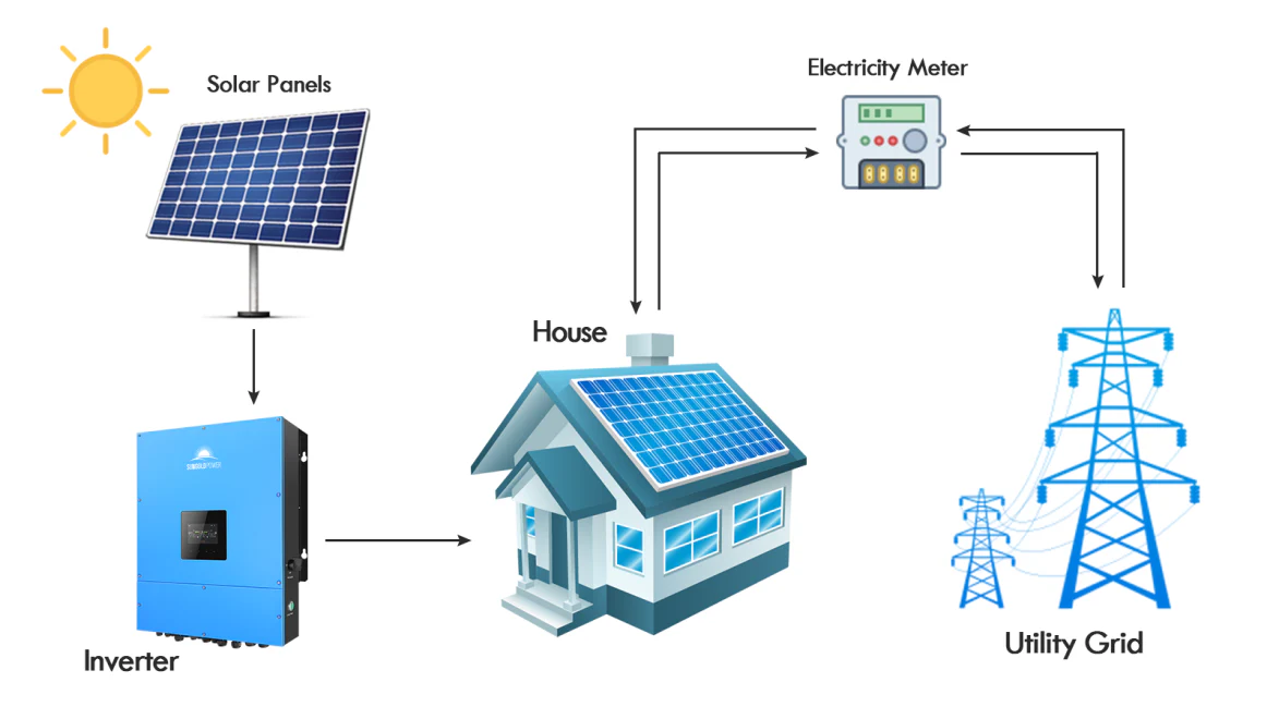
Myth: “If I have solar panels, I have power during an outage.”
-
Reality: Standard solar is “Grid-Tied” and shuts down during an outage for safety. You need a “Grid-Forming” inverter and a battery to stay powered.
-
-
Myth: “Batteries are too expensive for microgrids.”
-
Reality: When you factor in the “Cost of Downtime” for an industrial facility—which can be $10,000 per minute—the battery pays for itself in a single prevented outage.
-
-
Myth: “Microgrids are only for remote islands.”
-
Reality: Urban data centers and hospitals are the fastest-growing segment of the microgrid market due to macrogrid instability.
-
Conclusion
The integrity of a modern facility is inextricably linked to its “Electrical Sovereignty.” To master On-Site Microgrid Stabilization is to bridge the gap between the physical inertia of the past and the digital precision of the future. By prioritizing grid-forming technology, implementing tiered load-shedding hierarchies, and maintaining a rigorous governance cycle, organizations can insulate themselves from the increasing fragility of the macrogrid. In an era of non-linear climate and infrastructure risks, the most valuable asset a facility can own is a stable, autonomous heartbeat.